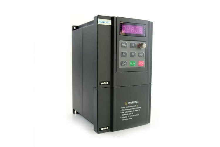
PLC is more and more widely used in industrial applications. Many online customers call to ask about the connection between PLC and inverter. In fact, PLC and inverter are a relationship of inclusion and inclusion. Both PLC and inverter can accomplish some things. A specific command used to control the motor. There are three methods for how the PLC controls the connection of the inverter:
1. Use the analog output module of the PLC to control the inverter
The analog quantity output module of PLC outputs 0~5V voltage signal or 4~20mA current signal as the analog quantity input signal of the inverter to control the output frequency of the inverter. The wiring of this control method is simple, but it is necessary to select a PLC output module that matches the input impedance of the inverter, and the analog output module of the PLC is expensive. When connecting, be careful to separate the wiring to ensure that the noise on the main circuit side will not be transmitted to the control circuit.

2. Use the switch output of PLC to control the inverter
The digital output of PLC can generally be directly connected with the digital input of the inverter. This control method has simple wiring and strong anti-interference ability. The switch output of PLC can be used to control the start/stop, forward/reverse, jog, speed and addition and subtraction time of the inverter, which can achieve more complex control requirements, but only step-by-step speed regulation.
When using relay contacts for connection, there may be malfunctions due to poor contact. When using a transistor for connection, it is necessary to consider factors such as the voltage and current capacity of the transistor itself to ensure the reliability of the system. In addition, when designing the input signal circuit of the inverter, it should also be noted that the improper connection of the input signal circuit may sometimes cause the malfunction of the inverter. For example, when an inductive load such as a relay is used in the input signal circuit, when the relay is opened and closed, the generated surge current may cause the malfunction of the inverter, which should be avoided as much as possible.

3. Connection between PLC and RS-485 communication interface
All standard inverters have an RS-485 serial interface (some also provide RS-232 interface), using two-wire connection, and its design standards are suitable for application objects in industrial environments. A single RS-485 can connect up to 30 inverters, and according to the address of each inverter or using broadcast information, the inverter that needs to be communicated can be found.
Tel/Fax: 0086-577-62840011
WhatsApp: 008613355775769
#inverter #forfrequencydrive #ACvfd #frequencyinverter #chinashuyi
#variablefrequencydrive #threephaseacinverter #variablefrequencyinverter
#3phaseinverter #achotsalefrequencyinverter #highvoltageacinverter #ZHSHUYI

