
The frequency converter is a “similar three-phase alternating current” that uses the switching and conduction of the IGBT to convert the direct current into a PWM wave with adjustable amplitude. The realization principle is to control the switching sequence of the IGBT through the three-way PWM wave output by the inverter CPU. There is a 120-degree phase angle between the three groups of PWM waves.

Now the #inverter basically adopts the AC-DC-AC mode, that is, the input AC is rectified to DC, and the #inverter is converted to AC. After rectification, the output phase sequence has nothing to do with the input phase sequence, and the output phase sequence can be conveniently controlled in the #inverter link. Only changing the input phase sequence of the inverter cannot change the direction of the motor. Changing the output phase sequence of the inverter can change the direction of the motor.
The steering can be adjusted inside the #inverter, and the parameters can be changed. Some #inverters can directly adjust a parameter to realize commutation. The synchronous machine needs to change the larger line and modify the angle. SIWE can correct the multi-function terminal of the forward and reverse, and can also directly exchange the input line of the forward and reverse.
Generally, the frequency converter is used to control the motor, which can control the number of revolutions of the motor, forward and reverse, etc. The greater the frequency, the greater the range of motor rotation. The size of the motor frequency can be adjusted. If you can’t adjust the parameters, you can change the output line sequence. It is possible to call out the line.
The #inverter motor adjustment reversal method is as follows:
1. Through the parameter setting of the inverter, use the software to operate the reverse direction. This is very easy to do, and the motor can be reversed without moving the hardware;
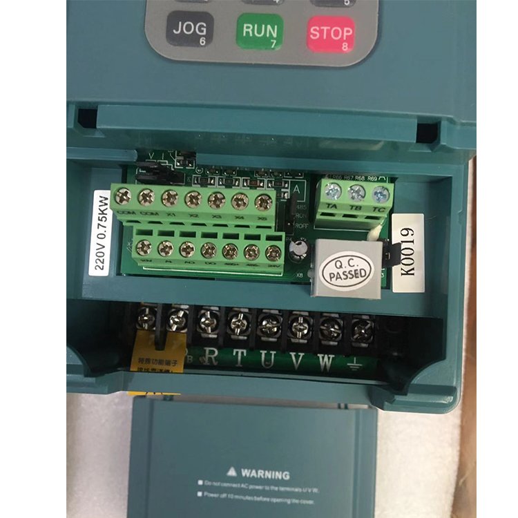
2. Reversal can also be achieved by commutating the phase sequence (reversing the line) of the output line of the #inverter to the motor. However, if the motor has encoder feedback, the line sequence of the encoder must also be reversed. Otherwise, the inverter will report a fault. The system without encoder feedback can only commutate the motor.
3. It should be noted that commutating the input line of the #inverter has no effect at all. Because, the input of the inverter has nothing to do with the commutation of the motor cable.
4. There is basically no wiring problem about the #inverter’s forward and reverse directions in the inverter’s manual. The digital input of the #inverter can be customized, that is to say, the function of each terminal can be edited, so you don’t have Finding one that does not mean that the forward and reverse functions cannot be realized.
5. The problem of the input and output terminals of the inverter, the digital input terminal of the #inverter is the external loop to send commands to the inverter, instructing the inverter to start and stop or other actions to achieve external control of the #inverter. The digital output terminal is the frequency converter can send out some function instructions, the most commonly used is running, fault status output. The output terminal of the inverter can reflect the working state of the #inverter and realize the internal self-defined function of the #inverter.
The #inverters on the market all support the function of reversing the motor directly through the panel buttons, external terminals and communication. This is optional, and the function of prohibiting the reversal of the motor can also be set. This reversal method is essentially realized by changing the direction of the excitation magnetic field of the motor. There is also a way to reverse the #inverter, which is used in special occasions, such as vector control occasions. It is not convenient to change the excitation mode to commutate, because the establishment of the magnetic field takes time. If the panel method is used To operate, there will be a time difference problem, and during vector control, it is required to maintain a certain torque output in real time to avoid problems caused by load fluctuations. In this case, it generally needs to be realized by the reverse of the speed signal given by the terminal analog quantity. It can be understood that the current on the “armature” is reversed, causing the corresponding magnetic field direction to change. Of course, the #inverter with vector control must be selected to have this function.
Tel/Fax: 0086-577-62840011
WhatsApp: 008613355775769
#VFD #INVERTER #frequencyinverter #frequencyconverter #converter #inverters #vfds #vfdmarket #vfdinverter #acdrive #frequencyconverter
#forfrequencydrive #vfddrive price #frequencyinverter #powervariablefrequencydrivevfd
