

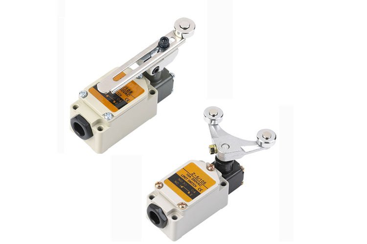
The structure of the travel switch is the same as the ordinary manual button and pedal button, but the external operating mechanism is different in form, including rotary and push-up. When the motion mechanism runs in place, it touches the operating mechanism of the travel switch, thereby driving the internal switch contacts to open and close.
It can be installed on relatively stationary objects (such as fixed frames, door frames, etc., referred to as still life) or on moving objects (such as vehicles, doors, etc., referred to as animals). When the animal approaches the still life, the connecting rod of the switch drives the contact of the switch to cause the closed contact to open or the open contact to close. The action of the circuit and mechanism is controlled by the change of the open and closed states of the switch contacts.

The travel switch uses the collision of the production mechanical moving parts to make the contacts move, so as to realize the connection or disconnection of the control circuit, thus playing a control role.
Generally, this type of switch is used to limit the position or stroke of mechanical movement, so that the moving machinery can automatically stop, reverse movement, variable speed movement or automatic round-trip movement according to a certain position or stroke.
Physical wiring method of travel switch
1. Use a screwdriver to remove 4 screws. Remove the cover and insulating pad. You can see the inside of the switch, it has 4 terminal screws.
2. Use the resistance gear of the multimeter to measure. The red and black test pens are respectively connected to the upper and lower wiring screws. At this time it is the same.
3. Measure the other two wiring screws as well. If the switch is not moved, the state is disconnected, that is, the position of the handle of the switch is the same position.
4. The wiring of the travel switch of this machine is 3, and the two AC contactors work by pulling its position. One of these 3 wires is the power wire, and the other two are the power leads of the two contactors. Therefore, short-circuit the two terminal screws to form a connected circuit.
5. At this time, connect the red wire, that is, the power supply, to the lower wiring screw, so that the lower wiring screw contacts have power supply when the switch is turned.
6. Then connect a blue wire to the upper wiring screw, which is actually the power lead of a contactor, or connect it to the left position.
7.Connect the remaining black wire to the corresponding position of the blue wire, the power supply of the two contactors will change the working state of the two contactors by pulling the switch position. That is, the wiring of the travel switch is completed.
Web: www.cnswitch.cn
Tel/Fax: 0086-577-62840011
Wechat/WhatsApp: 008613355775769
#limitswich #electricallimitswitch #elevatorlimitswitch
#tyerlimitswitch #safetylimitswitch #sealedlimitswitch
#shortlevertypelimitswitch #ZJSHUYI #chinashuyi
